Allen Bradley 800t Xa Wiring Diagram
Allen bradley 800t xa wiring diagram. 800t/h typical pilot light wiring diagrams 40 800h push button enclosures 41.
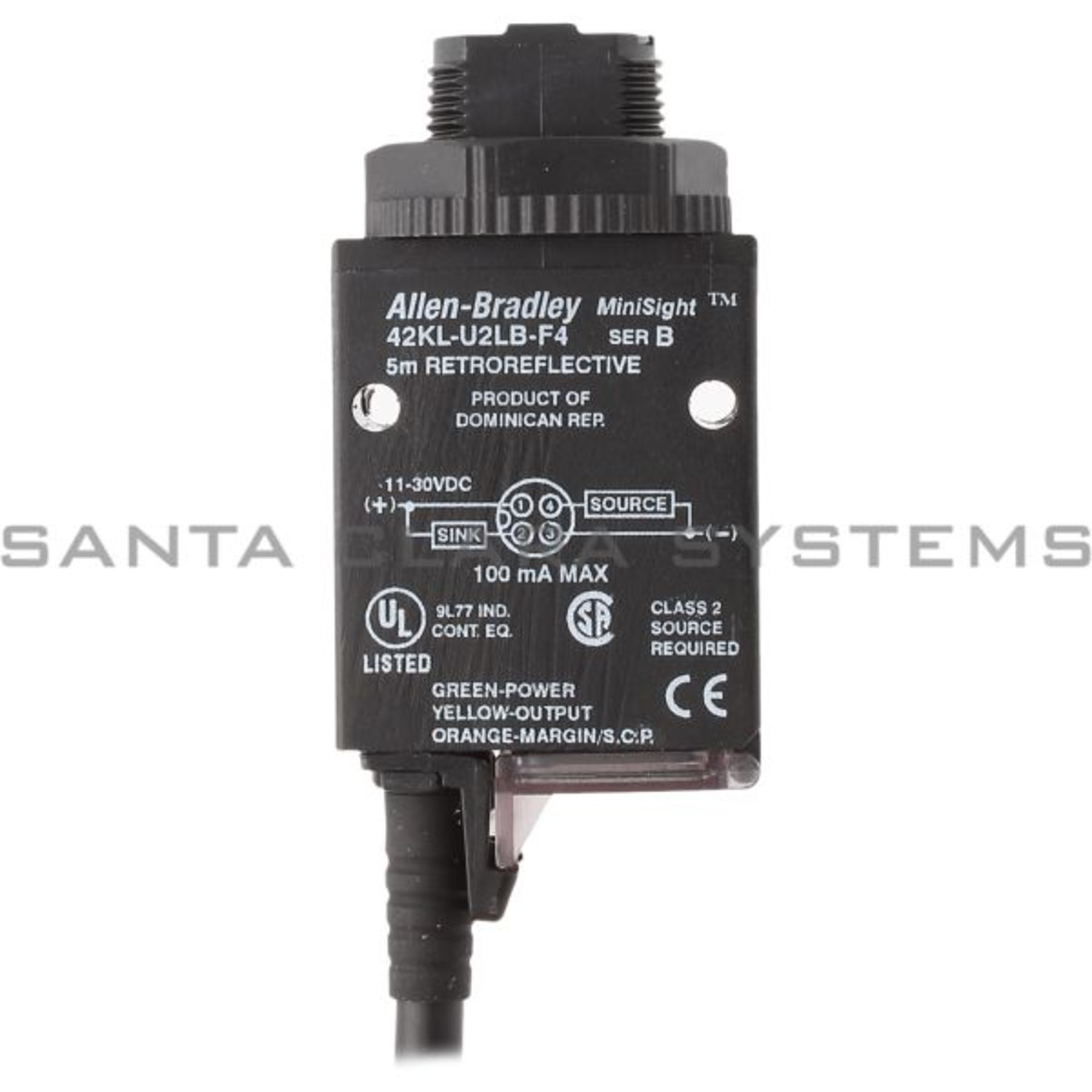
Allen Bradley Limit Switch Wiring Diagram
Nkcr, noiv) csa certified (file no.

Allen bradley 800t xa wiring diagram. Allen bradley 800t xa wiring diagram. Typical wiring diagrams for push button control stations. Each product page provides a collection of links to essential documentation to help you complete typical tasks.
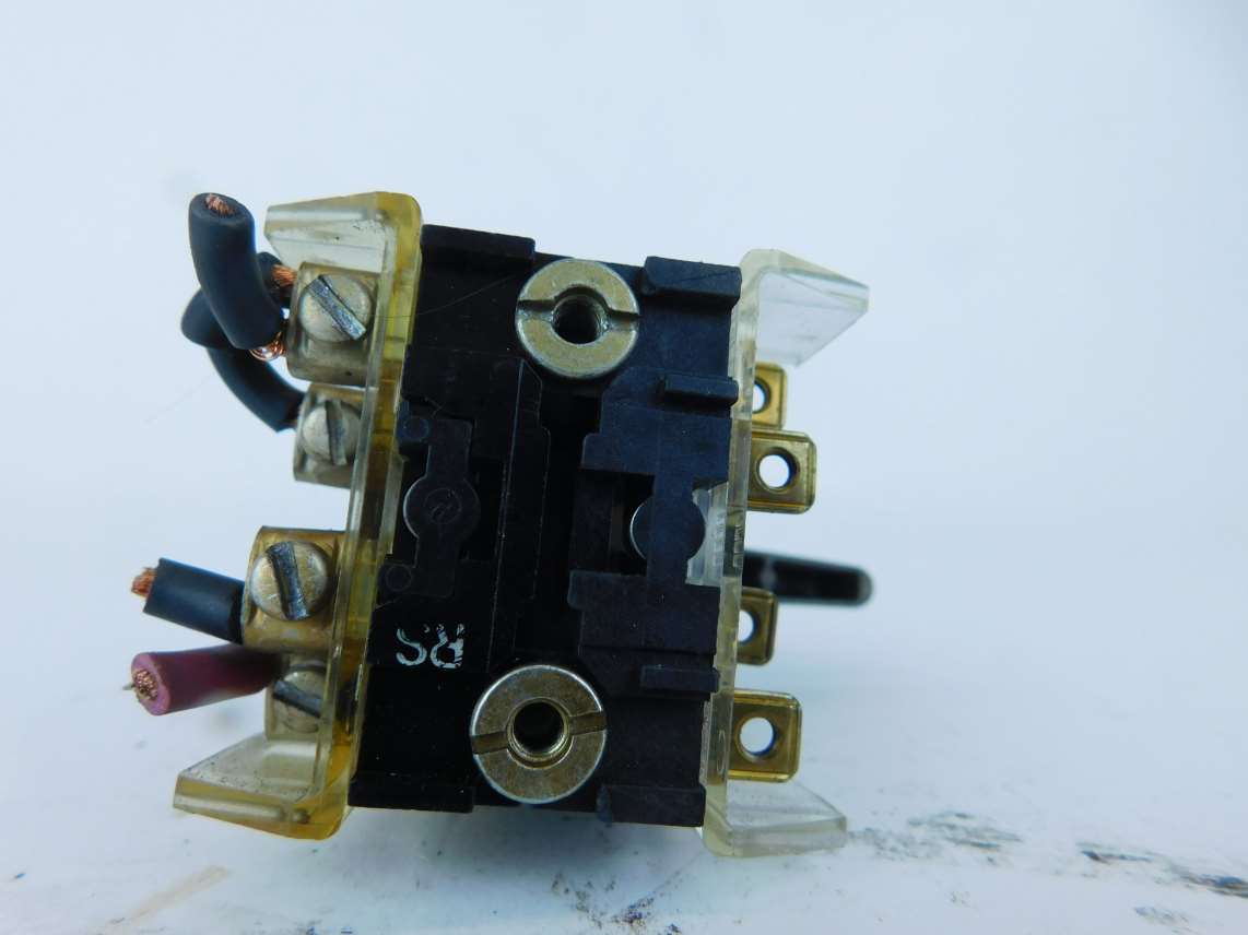
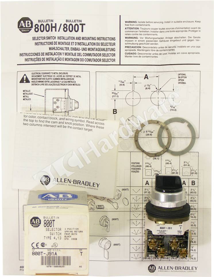
Identify the contact block used by looking at the contact block cover plate and finding a catalog no. Install on a flat, smooth surface of an enclosure. Allen bradley powerflex 70 wiring diagram.
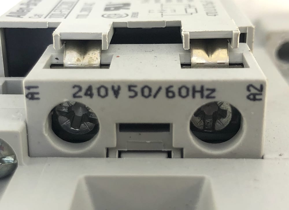
Humidity 50…95% rh from 77…140 °f (25. Standard contact ratings adjustment range: They are designed and constructed to perform in the most demanding industrial environments.
Lr1234, lr11924) csa c22.2, no. 3 phase motor auto starter circuit diagram. Allen bradley guardmaster safety relay wiring diagram.
They are designed and constructed to perform in the most demanding industrial environments. Square d manual motor starter wiring diagram. Exactly how the writer makes as well as develops every word to prepare as sentences, sentences as paragraph, and also paragraphs as publication are really amazing.
Browse technical documentation organized by product area. It does not restrict you to take a new method as well as mind to view concerning this life. Allen bradley 800t xa wiring diagram.
Browse the specification documents, installation instructions, user manuals, reference manuals, and related content on each page to find what you need. Lr1234, lr11924) csa c22.2, no. Wiring diagrams — touch button terminations general purpose electrical connections:
800t devices are rated type 4 and 13, 800h devices are rated type 4, 4x and 13. Devices maintain their type ratings only when properly mounted in an enclosure with the same rating(s). 800h & 800t) verlapping product data overview bulletin 800h and 800t, 3 & 4 position selector switches can be assembled with a variety of operators and contact blocks to achieve the desired target arrangement.
Diesel engine starter motor diagram. Nkcr, noiv) csa certified (file no. Wire gauge/terminal screw torque #18…14 awg (#18…10 max duty) / 6…8 lb•in typical operating forces.
150vac, 0.15a, 8va and 30vdc, 0.06a, 1.8va. Thanks god, this is an excellent time. Typical pilot light wiring diagram.
Yeah, lots of people have their particular in getting their favourite points.
AllenBradley 800TJ2 (800TXA) Switch GPM Surplus

AllenBradley 100C97D00 Contactor w/100S B Auxiliary
AllenBradley 800TXA2 Contact Block, 2 N.O., Series D eBay

ALLEN BRADLEY 800TH2 SELECTOR SWITCH SER. T W/ 800TXA

PLC Hardware AllenBradley 800TJ91A 30.5mm 3Position
800TXA ALLENBRADLEY, PUSH BUTTON CONTACT BLOCK 1N.O. 1N

PRODUCT OVERVIEW
Allen Bradley 800TXD1 Contact Block Series D eBay

HLV h power feed wiring picture needed.


Allen Bradley 800HHR2CY 2 Position Selector Switch New In

Wiring repairs for 1941 Monarch 10EE Page 2
Allen Bradley 100C97 Series A Contactor w/240 Vac Coil

AllenBradley X227742 Contact Block Switch Assembly for
Allen Bradley Limit Switch Wiring Diagram
800TXA ALLENBRADLEY, PUSH BUTTON CONTACT BLOCK 1N.O. 1N
Allen Bradley Switch Wiring Diagram Wiring Diagram Networks


I have a machine with a variable frequency drive. Need to
404 Not Found 1


PRODUCT OVERVIEW