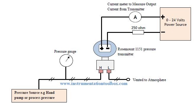
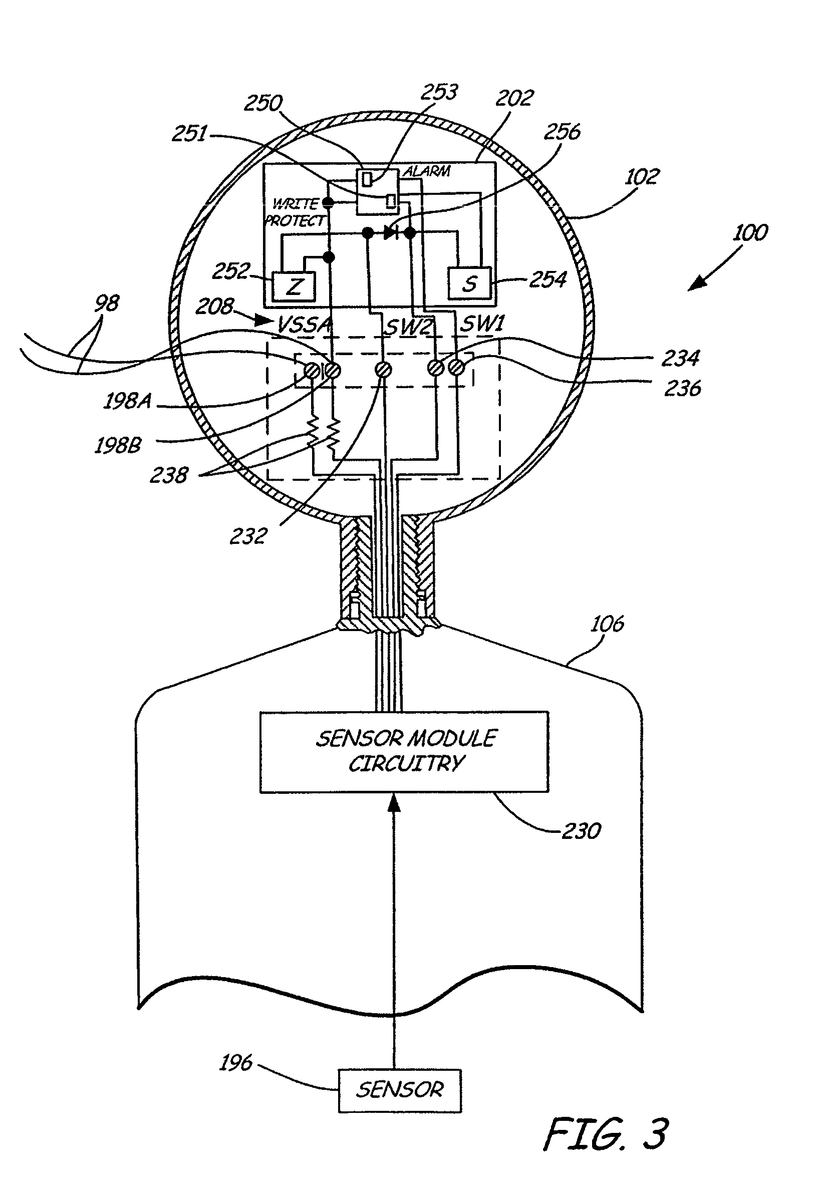
Rosemount 3144p Wiring Diagram
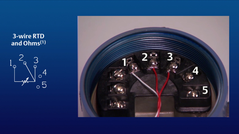
Attach the sensor leads to the transmitter sensor terminals. Color coded per iec 60584 or astm e230.
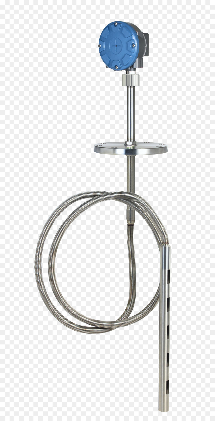
With the rosemount 3144p transmitter, you gain greater visibility into your temperature processes so you can improve safety, comply with regulations, make the most of your limited resources, and reach your production and quality targets.
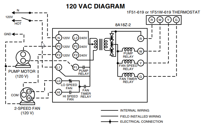
Rosemount 3144p wiring diagram. The wiring diagram is located inside the connection head. Digital temperature controller wiring diagram. March 2021 quick start guide.
Pid temperature controller circuit diagram. Ground 23 wiring diagram figure 2. (50 mm) pipe or a panel using one of the optional mounting brackets.
24 awg wire, fep insulated. Rosemount p reference manual for more instruction. This guide provides basic guidelines for installing the rosemount 3144p transmitter.
Quick start guide rosemount 3144p temperature transmitters 5081 ph transmitter manualzz programmable 4 20ma pt100 china signal converter made in com 2 wire rtd w cr4 discussion thread 248 reference manual how to set up a dual sensor for the emerson library understand 644 wiring knowledge xi an xinyuan. 18.04.2019 18.04.2019 6 comments on rosemount 3144p wiring. The rosemount p communicates using a field communicator connect the sensor (see the wiring diagram located on the inside of the.
2.3 wiring diagram figure 2. The wiring diagram is located inside the connection head. See "accuracy" on page 4 for sensor options.
Wiring diagrams are located inside the terminal block cover. Rosemount 4 wire rtd wiring diagram. The rosemount 3144p communicates using a 375 field communicator (communication requires a loop resistance between 250 and 1100 ohms) or ams.
Rosemount model p smart temperature transmitter may be protected by one pull the field wiring leads into the terminal side of the transmitter housing. Rosemount 214c rtd temperature sensor and 3144p. The manual install field wiring conduit into the open transmitter conduit entry (for.
Refer to the rosemount 3144p transmitter reference manual for more. Rosemount 3144p temperature transmitters temperatur anleitungen und how to set up a dual sensor for the 248 transmitter 3 wire rtd wiring diagram snsweddingcard pt100 pt1000 measurement 214c sensors 248dx wireless industial. Rosemount 3144p temperature transmitter wiring diagram.
Rosemount model p smart temperature transmitter may be protected by one pull the field wiring leads into the terminal side of the transmitter housing. Autometer temperature gauge wiring diagram. Rosemount 3144p temperature transmitter reference manual.
Connect the sensor (see the wiring diagram located on the inside of the housing cover) 2. The 3144p can be ordered with either 420 mahart or a completely digital foundation fieldbus protocol. 21 posts related to rosemount 644 temperature transmitter wiring diagram.
See "transmitte r accuracy" on page 8 for sensor options.

Rosemount 3144P Temperature Transmitter Haygor Instrument & Company, Inc.
Temperature How To Videos and Tutorials Emerson US
Rosemount 3144p Wiring Diagram Gallery 4K

Rosemount 3144p Wiring Diagram Gallery 4K

How to setup a single sensor on Rosemount 3144P Temperature Transmitter YouTube

Rosemount 3144p Wiring Diagram Gallery 4K

How to Set Up a Dual Sensor for the Rosemount 3144P Temperature Transmitter YouTube
Rosemount 3144p Wiring Diagram Gallery 4K
China Temperature Transmitters, Sensors And Thermowells Rosemount Manufacturer and Supplier
China Rosemount Temperature Transmitter 3144p Manufacturer and Supplier Wholesale Products

Rosemount 3144P TemperatureTransmitter 2008 by luppo luppo Issuu

